Functionality of Level 0 Data Flow Diagram and Its Elements
In every business process, there is a diagram called Level 0 Data Flow Diagram (level 0 DFD) that shows all the processes sequentially using the level of numbering. This diagram functionality is to show all major processes that are performed and related to the system, and how they can relate to each other with the data that pass among them. In making a business process model, there will be only one level 0 DFD. The functionality of level 0 DFD can be drawn using some elements and shown with the function of each elements, which are as the following:
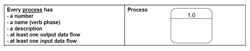
- Each processes that are drawn in the level 0 DFD has a function to show which major computerized activities are performed in a specific business process. Every process should be numbered in a sequential order, for example (1.0, 2.0, etc.). The purpose is to let know which activity that occurs first before the others. The name of each process should represent enough information for the reader to let them understand the activity that they should do. Inside one process, we can write several activities with “and”, which shows that one process that have more than one functionality
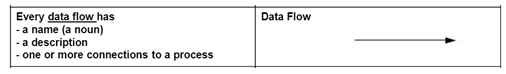
- Next is data flow. As what the diagram is named, each level 0 DFD must have data flow to show the interactions among them. Each data flow contains information that flows inside the level 0 DFD processes and the arrow shows which direction the data goes from or to the process. This element is strongly related to the process because each process should at least produce or receive one data flow for the business process to work.
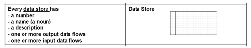
- Function of each data store in a level 0 DFD is to be the collection of information that are stored or retrieved by the data flow to link to the process. This element has the same strong relationship with input or output data flow. A data store should at least have one input or output data flow to show what information that are inputted or retrieved through the process
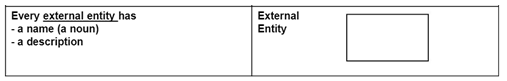
- Lastly is external entity. This element represents a person, organization unit, or system that interacts with the system and also the one who only give or receive data from the system or can be simply said external to the system. External entity can be counted as the part or not the part the organization because those who receive or use information from the system are counted as the external entity of a level 0 DFD.
The other principle in making a level 0 DFD is to maintain the balance. Balance means the functionality of all information are presented accurately and appropriately. There are 3 major mistakes that causing the level 0 DFD is unbalance:

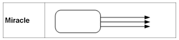
- This means the function of data flow is not appropriately used because it only has the input data flow to the process, but there are no outputs
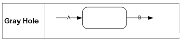
- This is the reverse of black hole. The inputted data flow does not exist, but there are output data flow from the process which is impossible because we do not know what data that are processed until becoming output data flow
- This last illegal mistake occurs when the inputted data flow and the output data flow is not the same. This means the functionality of the data flow element is not used properly to show all of the data flow inside the level 0 DFD
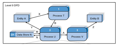
This figure will show the complete usage example of the elements above: