

Functionality and The Way to Develop a System Sequence Diagram
There is another way to develop describing system functionality besides using use case diagram and use case description. It is called System Sequence Diagram (SSD), which represents a diagram based on the use case that we have made and shows the messages between an actor and the system sequentially (Satzinger, Jackson, & Burd, 2012). This diagram is usually used to describe the flow of input and output messages or information that come across the system, so it can be called as an interaction diagram.
When a SSD is made, it is made based on a single use case or use case description because the function is to make us easier to identify an input or output that happens through a system in a single use case. The way to develop a SSD is divided into 4 steps (Satzinger, Jackson, & Burd, 2012):
- Identify the input messagesFor the first step, identify which activities are related to the system, or we can identify from the flow of activity for use case. Those activities show which area that need data or information to be inputted because it crossed the system boundary.
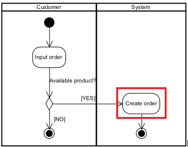 For this activity diagram for use case “Create Order” for a glasses store, we can see that Create Order across the system boundary, so we can identify it as a single use case or activity that needs input messages.
- Describe the message from the actor into the system
It is used to know about which information inputted by the actor through the system, so we can know the flow of information needed for this single use case. As for the example, we will use the “Create Order” use case.
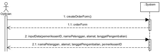
From this example of SSD, we can see what kind of information needed from the actor (optician) to input information into the system
Identify any special conditions in the input messages, including iteration
For the third step, the function is to identify which message is having a special condition, such as repetition or iteration.
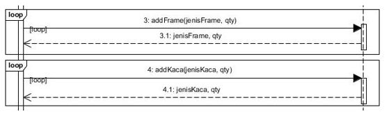
As for this example, we use looping frame on Frame and Glass Type because in the case, customer can choose more than one frame and glass type in one same transaction. So, its function of each message, tells us about the special condition when we do the “Create Order” use case.
- Identify and Add the output or return messages
The return message is the one that come back from the system to the actor with a dashed arrow or we can say it as the output from the system. We can find the clue about what information that will be the output from activity diagram or the flow of activities in use case description. Each return message will be named in noun to indicate what is being returned
 In this case example, the output messages are functioned as a notification given back to the actor by the system, after the actor enter the input messages.
After we follow the 4 steps above and know the functions of each step, now we can identify and make a System Sequence Diagram (SSD) to help us in better understanding about the data flow that are needed from the actor to the system.
Reference:
Satzinger, J. W., Jackson, R. B., & Burd, S. D. (2012). Systems Analysis and Design. Boston: Joe Sabatino.
Comments :