State Machine Diagram
A good system must have an ability to provide its user with useful information. It includes maintaining information about the status of problem domain objects. Before providing useful information to its user, the domain objects that require checking and business rules that determine valid status conditions need to be identified.
State of the object refers to the status condition for an object. In a clearer definition, a state of an object is a condition that occurs during its life when it satisfies some criterion, performs some action, or waits for an event (Satzinger, Jackson, and Burd, 2012). For general objects, we can equalize the state of an object with its status condition.
Status condition’s convention name helps identify valid states. Status condition might be simple, so we can give the name of its status in an understandable name such as Off or In Repair Progress. Names consisting of gerunds or verb phrases can be given in other states which are more active, such as Being recorded or Printing. For example, a specific Sale object in a restaurant comes into existence when a customer orders something. Right after it is created, the object might be in a state called Adding new order, then a state called Waiting for orders to be served, and at the end, when all orders have been served, a state called Completed.
An object cannot move to another state until some event causes it to do so. Analysts use the mechanism as a result of the combination of states and transitions between states to capture business rules. The information which is captured and documented in a UML diagram called a state machine diagram.State machine diagram can be defined as a diagram showing the life of an object in states and transitions.
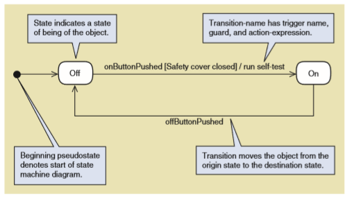
Figure below shows the notation of state machine diagram:
Here is the 8 steps to get started in developing state machine diagram (Satzinger, Jackson, and Burd, 2012):
- Review the class diagram and select the classes that might require state machine diagrams. In this step, analysts have to include classes that have multiple status conditions which are important to be tracked by system. Right after doing that, begin with classes that appear to have the simplest state machine diagram.
- For each selected class in the group, make a list of all the status conditions you can identify. Brainstorming is the activity that must be done in this step to make sure that the states for the real-world objects that will represented in a software system.
- Begin building state machine diagram fragments by identifying the transitions that cause an object to leave the identified state. For example, if a sale is in a state of Ready to be served, a transition such as startServing will cause the order to leave that state.
- Sequence these state-transition combinations in the correct order. In this step, assembly the combinations into larger fragments.
- Review the paths and look for independent, concurrent paths.
- Look for additional transitions. Then, take every paired combination of states and ask whether there is a valid transition between the states.
- Expand each transition with the appropriate message event, guard-condition, and action-expression.
- Review and test each state machine diagram. Evaluate the state machine diagram to make sure all the states and objects well-defined. After doing the evaluation, refinement of the diagram might be necessary if it does not fit with the actual event or information.
Reference:
Satzinger, J. W., Jackson, R. B. & Burd, S. D., 2012. Systems Analysis and Design: In a Changing World. Boston: Cengage Learning.